

"When installing cylindrical linear shafts, what parallelism tolerance should be maintained?""Why do different equipment types have varying parallelism requirements for cylindrical linear shafts?""What are the consequences of exceeding parallelism tolerance, and how can it be precisely controlled?"As an engineer with 12 years of experience in installing precision linear transmission components and managing accuracy control, the core of these questions lies in achieving "precise alignment between parallelism requirements and equipment operating conditio What are the consequences of parallelism exceeding specifications, and how can it be precisely controlled?" As an engineer with 12 years of experience specializing in the installation and precision control of precision linear transmission components, the core of these questions lies in "accurately matching parallelism requirements with equipment operating conditions and precision demands." As a core guiding component in precision machine tools, automated equipment, and linear modules, the installation parallelism of cylindrical linear shafts directly determines the smoothness of linear motion, guiding accuracy, and component service life. Unclear parallelism requirements often lead to installation errors. Conversely, precise understanding and strict control of parallelism ensure linear motion accuracy, reduce maintenance costs, and enhance overall equipment reliability. Today, we'll guide you through an 8-step framework to fully grasp the parallelism requirements for installing cylindrical linear shafts. From core concepts to post-installation maintenance, we'll clarify the standards, control methods, and practical points for each stage, achieving the goal of "accurate parallelism compliance and stable equipment operation."
Step 1: Comprehensive 8-Step Analysis of Parallelism in Cylindrical Linear Shaft Installation
Define Core Parallelism Concepts-First Understand "What Parallelism Essentially Is"
To accurately grasp parallelism requirements for cylindrical linear shaft installation, first clarify its core essence, key impacts, and fundamental constraints. Avoid common pitfalls like "strict parallelism is always better" or "ignoring application-specific adaptation":
- Core Definition: Parallelism in cylindrical linear shaft installation refers to the degree of parallelism between two or more parallel-mounted linear shafts (or between a linear shaft and a reference surface) across their entire axial length. It is typically expressed as "deviation per meter (mm/m)" or "total deviation over full stroke (mm)." Its core function is to ensure uniform force distribution during slider movement along linear axes, preventing jamming and uneven wear while guaranteeing guidance accuracy and smooth linear motion.
- Core Parallelism Value: 3 Key Functions Ensuring Reliable Linear Transmission:
- Smooth Motion: Meeting parallelism standards prevents vibration and stuttering during slider movement while reducing operational noise;
- Precision Assurance: Ensures positioning accuracy and repeatability in linear motion, preventing trajectory deviation caused by parallelism deviations;
- Extended Lifespan: Reduces localized excessive wear between the slider and linear shaft, prolonging the service life of both components.
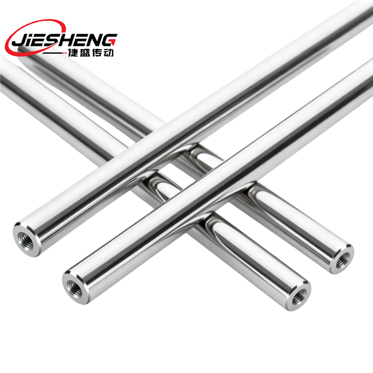
Step 2: Core Impacts of Excessive Parallelism-Understanding "Why Parallelism Must Be Controlled"
Excessive parallelism during cylindrical linear shaft installation triggers a chain reaction of issues, from abnormal motion to component failure, severely impacting equipment operation. Core impacts include:
Degraded Motion Performance: Stuttering and vibration during slider movement, with significantly increased operational noise (typically exceeding 75dB); resonance prone to occur during high-speed operation, causing trajectory deviation and reduced positioning accuracy.
Excessive Component Wear: Excessive parallelism causes uneven force distribution between the slider and linear shaft, increasing localized pressure and significantly accelerating wear rates. It also intensifies wear on internal balls/rollers within the slider, shortening its service life.
Structural stress damage: Prolonged uneven loading induces additional structural stress between the linear shaft and mounting base, causing base deformation and shaft bending. Severe cases may result in component fracture, triggering equipment shutdown failures.
Step 3: Fundamental Parallelism Requirements for Cylindrical Linear Shaft Installation - General Standards and Core Parameters
While no universally absolute standard exists for parallelism requirements in cylindrical linear shaft installation, industry-wide foundational standards apply. Core requirements depend on shaft specifications and precision grades while adhering to relevant national standards. Key foundational requirements are as follows:
Core Reference Standards:
- GB/T 1184-1996 "Shape and Position Tolerances - Unspecified Tolerance Values": Defines unannotated tolerance requirements for parallelism in linear transmission components; applicable for standard-precision equipment.
- GB/T 30412-2013 "Linear Motion Rolling Supports - Cylindrical Linear Guide Pairs":
Establishes specialized installation accuracy requirements (including parallelism) for cylindrical linear guide pairs, serving as the core compliance standard for precision equipment installation.
Step 4: Parallelism Requirements for Cylindrical Linear Shafts by Application Scenario-Precise Matching to Operational Demands
Equipment across different industries and operating conditions exhibits significant variations in parallelism requirements for cylindrical linear shaft installation. Precise matching to specific operational scenarios is essential. Core scenarios and corresponding requirements are as follows:
General Conveying and General Machinery Scenarios:
- Compatible Equipment: Belt conveyor lines, warehouse rack translation mechanisms, manual lifting platforms, etc.;
- Application characteristics: Low speed (≤0.5m/s), light load (≤500N), low positioning accuracy requirements (allowable deviation >0.1mm);
- Parallelism requirements: ≤0.08-0.10mm/m, total deviation over full stroke ≤0.30mm (stroke ≤3m).
Step 5: Installation Methods for Precise Parallelism Control-Practical Key Points and Core Techniques
To meet corresponding parallelism requirements, mastering scientific installation methods is essential. Precise control must be applied throughout all stages-from installation benchmarks and adjustment techniques to fixing methods. Core approaches include:
Precise Selection of Installation Benchmarks:
- Prioritize the equipment's own machined reference surfaces, where surface flatness must exceed half the parallelism requirement;
- When no suitable reference surface exists, employ the "reference axis method": First install one linear axis as the reference axis, ensuring its straightness meets specifications. Then install other linear axes using this reference axis as the alignment benchmark.
Stepwise Parallelism Adjustment:
- Initial Positioning: Place the linear axis on the mounting base and lightly pre-tighten the bolts to allow slight movement of the linear axis;
- Precise measurement: Using a dial indicator or micrometer, uniformly select measurement points along the entire length of the linear axis to measure the parallel deviation between the linear axis and the reference surface/axis.
- Fine-tune correction: Based on measurements, progressively align the linear shaft by adjusting the mounting base's shims or adjustment screws until parallelism deviation meets requirements at all measurement points;
- Secure locking: After achieving parallelism, progressively tighten bolts in a diagonal sequence. Continuously verify parallelism during tightening to prevent positional shifts caused by clamping force.
Step 6: Parallelism Verification Specifications-Acceptance Criteria and Inspection Methods
After installation, conduct standardized verification to confirm parallelism compliance. Define inspection tools, procedures, and acceptance standards as follows:
Core Inspection Tools:
- General-precision inspection: Use dial indicator + magnetic base for scenarios requiring parallelism >0.02mm/m;
- Precision Inspection: Use a dial indicator or laser interferometer for scenarios requiring parallelism ≤0.02mm/m.
Standard Inspection Procedure:
- Tool Installation: Secure the magnetic base to the reference surface or reference axis. Position the dial indicator probe vertically against the surface of the linear axis being measured, maintaining a preload of 0.2-0.5mm.
- Full-Stroke Measurement: Slowly move the base, taking uniform measurements across the entire length. Record the deviation value at each measurement point.
- Deviation Calculation: Calculate the deviation difference between adjacent measurement points to determine the deviation per meter. Calculate the maximum deviation difference and minimum deviation difference across the full stroke to determine the total deviation over the full stroke.

Step 7: Common Parallelism Control Pitfalls and Avoidance Methods - Precisely Steer Clear of Pitfalls
During installation, common pitfalls like "neglecting reference accuracy" or "failing to recheck after locking" can lead to parallelism non-compliance. Targeted avoidance is essential:
Misconception 1: Neglecting installation reference accuracy leads to inherently inadequate parallelism
- Manifestation: Using rough installation surfaces as references. When reference surface flatness exceeds tolerances, parallelism cannot be achieved even after repeated adjustments.
- Solution: Inspect the reference surface flatness before installation. If it fails to meet standards, re-mill or grind the reference surface to ensure its accuracy exceeds half the parallelism requirement.
Misstep 2: Fully tightening bolts in one go, causing adjustment failure
- Manifestation: After adjustment, bolts are fully tightened without re-verification. The clamping force shifts the linear axis position, resulting in parallelism exceeding tolerance.
- Prevention Method: Employ a "step-by-step tightening and repeated verification" approach.
Step 8: Post-Installation Parallelism Maintenance and Re-testing-Ensuring Long-Term Stability
Achieving parallelism compliance is not a permanent solution. During operation, factors like vibration, temperature, and wear may alter parallelism, necessitating a regular maintenance and re-inspection mechanism:
Regular parallelism re-inspection:
- Standard equipment: Re-inspect every 6 months;
- Precision equipment, high-speed heavy-load equipment: Re-inspect every 3 months;
- If re-inspection reveals parallelism deviation, promptly shut down for adjustment.
Key Daily Maintenance Points:
- Regularly clean dust and debris around linear shafts and mounting bases to prevent uneven force distribution from accumulation;
- Inspect the tightness of mounting bolts. Tighten any loose bolts immediately and recheck parallelism after tightening;
- Periodically lubricate linear shafts with grease to reduce wear and prevent increased parallelism deviation due to wear.
Conclusion: Cylindrical Linear Shaft Installation Parallelism - "Precision Matching is Core, Full-Process Control is Key"
Parallelism requirements for cylindrical linear shaft installation lack a fixed universal value. The core principle is "precise alignment with equipment accuracy demands and operational conditions"-standard equipment may tolerate 0.08–0.10 mm/m, precision equipment requires strict control at 0.008–0.02 mm/m, while high-speed heavy-duty equipment demands further refinement to 0.005–0.01 mm/m. Common user misconceptions include: "blindly pursuing excessively strict parallelism increases installation costs," "neglecting benchmark accuracy and locking verification leads to parallelism failure," and "post-installation neglect causes later failure."
In reality, following the 8-step analysis outlined in this article ensures long-term compliance: first, clarify core concepts and fundamental requirements for parallelism; then precisely match parallelism standards to specific scenarios; control parallelism through scientific installation methods; and finally establish regular maintenance and re-testing mechanisms.
This approach guarantees sustained parallelism compliance and ensures stable equipment operation. If you require a tailored parallelism control plan, provide key details such as "equipment type, linear shaft specifications, operating speed, load capacity, and positioning accuracy requirements" to obtain specific parallelism specifications, installation methods, and inspection standards. For existing installations, use this article's inspection protocols and common pitfalls to verify parallelism compliance and implement timely adjustments. Remember: Controlling parallelism during cylindrical linear shaft installation hinges on "reasonable requirements, scientific installation, and long-term maintenance." Precise control at every stage is essential for achieving stable and reliable equipment operation.
Contact Us
📧 Email: lsjiesheng@gmail.com
🌐 Official website: https://www.automation-js.com/


