

In precision linear motion applications such as servo feed axes, CNC slides, automated inspection platforms, lithium-ion battery packaging equipment, precision transplanting modules, and small CNC feed mechanisms, installation methods that rely on simple, direct mounting without calibration, improper mounting of support brackets, or lack of pre-tension compensation exhibit significant shortcomings in terms of coaxiality maintenance, transmission stiffness, long-term positioning stability, and control of temperature rise and thermal deformation. Extensive on-site maintenance statistics show that when the support brackets at both ends of the lead screw are locked in place without fine-tuning and calibration-and with an axial parallelism deviation of 0.02 mm/m-high-frequency reciprocating operation continuously generates additional bending moments. After 1,500 hours of service, wear in the ball circulation channels intensifies, and the risk of pitting and seizing in the raceways increases by more than 70%; In standard assemblies with non-preloaded supports, where internal bearing clearance is not eliminated, axial clearance gradually increases under directional change impacts, causing positioning errors to accumulate by 0.03–0.08 mm. This directly leads to inaccurate servo positioning, origin drift, and feed jitter; Conventional assembly solutions that rely solely on couplings to compensate for deviations lack an independent calibration process. This concentrates the load on the coupling's elastic elements, making them highly susceptible to fatigue fracture and coupling slippage-resulting in lost steps-under frequent forward-reverse impact conditions; Some low-cost assembly solutions omit the no-load running-in and temperature rise verification processes. Since bearing preload parameters do not match operating conditions, thermal expansion caused by temperature rise cannot be accommodated, leading to compressive buckling of the shaft system. As a result, actual positioning accuracy during operation is only about 40% of the design specification, failing to meet the stringent requirements of precision feeding-which demand long-term low vibration, stable reference points, and controllable thermal deformation.
Ball screw assemblies serve as the core transmission reference unit that converts the torque output of a servo motor into linear thrust. The ultimate performance of the entire transmission system is highly dependent on installation process specifications. Mainstream support configurations include Fixed-Support (BK-BF), Fixed-Fixed (BK-BK), and Fixed - free. These are suitable for general-purpose applications with lead screw outer diameters ranging from Φ6 to Φ63, and precision grades include standard rolled C7 and precision ground C5. The base material for the entire lead screw assembly is chromium-molybdenum alloy steel. It undergoes the following processes in sequence: blank tempering and quenching, raceway superfinishing, ball circulator assembly, bearing pairing and preloading, and seal and chip scraper assembly. Through installation processes featuring step-by-step calibration, preload adjustment, and thermal expansion compensation, the system ensures that the lead screw axis, guideway reference, and the geometric and positional tolerances of the motor output shaft are controllable in a closed-loop system, eliminating the need to rely on a coupling to forcibly compensate for large misalignment deviations. By leveraging the dual characteristics of precise alignment reference positioning and bearing preload stiffness control, it stably transmits axial thrust and maintains coaxiality between the motor output shaft and the lead screw input end. This effectively reduces additional bending moments on the coupling, minimizes localized contact stress on the balls, stabilizes the dynamic positioning accuracy of the servo system, and prevents typical failures such as backlash, transmission resonance, abnormal raceway wear, and positioning accuracy drift caused by assembly defects or inadequate process control. With features such as consistent installation reference, controllable bearing preload, compensable thermal deformation, a wide range of mounting options, and low vibration transmission, this solution is widely applicable to transmission scenarios with extremely high requirements for ball screw installation reference stability and impact resistance, such as CNC feed slides, lithium-ion battery packaging fixtures, automated sorting and conveying mechanisms, and optical inspection displacement stages.
|
|
Product Highlights
The core installation principles for ball screw assemblies are: cleaning the reference surface first, step-by-step calibration of supports, graded control of bearing preload, and compensation for thermal expansion over long strokes. These represent the fundamental differences at the installation level compared to simple direct-mount or non-alignment assembly solutions. Setting aside marketing rhetoric, and based on extensive bench assembly verification and field transmission operation and maintenance data, four key process advantages have been identified:
A single reference-based alignment of the support brackets and guide rails ensures stable coaxiality and eliminates off-center loading across the entire lead screw stroke. Precision-grade assembly employs a dial indicator for full-stroke synchronized calibration, adjusting the positions of both support brackets relative to a single reference point. This controls the parallelism between the lead screw axis and the linear guide within 0.02 mm/m, thereby avoiding cumulative positioning errors caused by unilateral locking. After the lead screw begins operation, the ball bearings experience uniform force distribution, preventing periodic lateral off-center loading and reducing the risk of bending stress in couplings and raceways, as well as alternating wear on guide rails and sliders, from the source.
Graduated bearing preload control combined with long-stroke pre-stretch compensation suppresses deformation caused by temperature rise. For high-speed, long-stroke fixed-to-fixed assemblies, pre-stretch is set based on pre-calculated thermal expansion to absorb axial elongation caused by temperature rise during continuous operation. This reduces compressive stress resulting from assembly lockup and eliminates issues such as lead screw bending, vibration and abnormal noise, and bearing overload damage caused by thermal expansion jamming.
The multi-support structure employs a differentiated installation approach to accommodate conventional, high-speed, and vertical lifting applications. Fixed-Support BK-BF Assembly: The floating end retains a slight axial clearance, suitable for stroke lengths ≤1000 mm and medium-speed feed applications; Fixed-Fixed BK-BK Assembly: Angular contact bearings at both ends are preloaded in pairs and must be used with pre-stretch compensation; suitable for long-stroke, high-speed, and high-rigidity applications; Fixed-Free assembly, with bearings constrained at only one end, is suitable for short-stroke, light-load vertical lifting applications; however, due to its low resistance to overturning, it is not recommended for horizontal feed applications.
After assembly, perform a no-load run-in and re-measure accuracy to ensure a stable baseline for long-term operation. After assembly, manually rotate the system through its full stroke to check for any binding. Perform a 30-minute low-speed, no-load run-in, monitoring the temperature rise of the bearings and lead screw. Once the steady-state temperature rise meets specifications, remeasure the reverse clearance and repeatability. After multiple start-stop cycles, precision degradation is less than 12%. Compared to a one-time locking solution without calibration, this significantly reduces precision drift and equipment failure rates in linear motion systems.
At the same time, the operating condition limits based on installation specifications are objectively defined: For feed axes with extremely high linear speeds, a fixed-to-fixed preload configuration must be selected to avoid the risk of thermal expansion instability; for vertical heavy-load applications, medium-preload matched angular contact bearings are preferred, as light preload configurations can easily amplify reversal clearance; In environments with heavy dust or coolant splashes, the nut must be equipped with a dust-proof and chip-removal scraper plus a telescoping dust cover; otherwise, the unsealed raceway is prone to rust and abrasive wear; ball screw installation and calibration can only correct assembly deviations and cannot compensate for deformation of the machine frame's reference surfaces; Extremely high-frequency impact conditions require vibration-damping structures; even if alignment accuracy is within specifications, it is necessary to prevent resonance between the support block and the machine frame from amplifying vibrations.
Core Installation Mechanism of the Product
The installation mechanism of ball screw assemblies differs from the direct locking assembly logic used for ordinary shafts. Relying on the rolling friction transmission characteristics that convert torque into linear thrust, the process follows a staged assembly workflow: reference surface cleaning → rough positioning of support brackets → insertion of the screw into the bearing unit → fitting and locking of the nut housing → coaxial parallelism calibration → preload / pre-stretch adjustment → seal and lubricant assembly → no-load run-in verification. This step-by-step assembly process addresses the four major engineering challenges commonly found in ball screw drives-reference surface misalignment, bearing clearance, thermal expansion-induced sticking, and positioning drift-from the very beginning of assembly, ensuring controllable alignment accuracy, stable transmission stiffness, and closed-loop control of load distribution within the shaft system.
Breaking down the assembly process logic: support bearings are paired and sorted at the factory; prior to assembly, the frame reference surface is cleaned to remove burrs and metal shavings; the support housing is pre-tightened without being fully locked, leaving room for fine adjustment; after calibration is complete, it is fully tightened and a locating pin is inserted to lock the reference; The alignment process relies on a dial indicator and a torque wrench to ensure geometric and positional tolerances are met. Under a single reference plane, the parallelism of the lead screw and the coaxiality between the motor and the lead screw are controlled to guarantee that the geometric and positional tolerances of all transmission components meet the drawing specifications. In a simplified assembly process, which lacks step-by-step alignment and preload control, the support housing is locked directly. When temperature rises cause the lead screw to elongate, this elongation cannot be accommodated, resulting in uneven force distribution on the balls and causing instantaneous loss of coaxiality. Precision Fixation-In this assembly solution, both end bearings are preloaded with no axial play. Pre-tensioning offsets thermal expansion, reduces the compensatory load on the coupling, and minimizes wear caused by sustained off-center loading on the flexible coupling. Through a step-by-step calibration and composite assembly process, the positional accuracy of the support bracket, nut bracket, and motor bracket is standardized. Reversal impact loads are evenly distributed to the frame, eliminating local stress concentration and preventing issues such as lead screw bending and abnormal raceway wear caused by insufficient rigidity in simple assembly.
Under conditions of continuous reciprocating feed and high-frequency start-stop operations, the lead screw is constantly subjected to inertial impacts from the slide, alternating axial thrust, and thermal expansion caused by temperature changes. If support misalignment exceeds specifications or bearing preload parameters do not match operating conditions, thermal expansion caused by temperature rise cannot be properly released, making the shaft system highly prone to periodic jamming and positional drift. A proper installation process prioritizes parallelism and coaxiality calibration. This ensures high dimensional stability in the finished drive system. Combined with a chip-scraping seal structure that prevents dust and coolant from entering the raceways, it consistently maintains the parallelism between the lead screw axis and the guideway within the permissible tolerance range. At the same time, the inherent stiffness of the paired angular contact bearing support structure is stable, which suppresses reverse-direction backlash, reduces the amplification effect of impact loads, and enhances the dynamic operational stability of the servo axis system. Compared to direct-mount solutions without calibration, there are no additional bending moments caused by forcibly bending the lead screw; compared to assemblies with non-preloaded supports, bearing clearance is controllable, so the gap does not continue to increase under temperature-varying conditions, and premature raceway failure does not occur during long-term feed operations.
A cross-comparison of the shortcomings of various suboptimal assembly methods reveals: in direct lock-in support block assemblies without a calibration process, parallelism errors are uncontrollable, causing the balls to be subjected to continuous lateral forces and exacerbating impact wear during start-stop cycles; in assemblies without preloaded bearings, internal bearing clearance allows the gap to open during direction changes, resulting in significant positioning drift;assembly with excessive preload causes an increase in bearing friction torque and a sharp rise in temperature, accelerating bearing fatigue failure; omitting the run-in verification during assembly prevents hidden stresses from being released in advance, leading to a concentrated outbreak of failures after the equipment is officially put into operation. The ball screw assembly solution-which incorporates step-by-step calibration, graded preload, and upfront thermal compensation-balances alignment accuracy, support stiffness, thermal deformation compensation, and structural compactness. It is currently the most balanced and standardized assembly solution in terms of process stability for precision linear feed systems.
Its core engineering value can be summarized as follows: by controlling transmission deformation through a assembly process involving step-by-step calibration, bearing preload, and thermal elongation compensation, it standardizes the reference tolerances of fixtures and gauges, locks the reference position for screw installation, and eliminates the risks of alternating lateral stresses, resonance, and reverse backlash in the shaft system caused by poor assembly. thereby ensuring long-term synchronization between the motor and the lead screw drive, and significantly enhancing the operational stability and overall service life of the linear feed system.
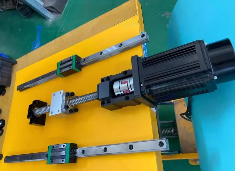
Product Showcase
Product Structure and Installation Process Parameters
The ball screw assembly serves as the standard structure for rolling-friction linear transmission. The installation process is managed across four key dimensions: coaxial parallel alignment, bearing preload stiffness, thermal expansion compensation, and sealing protection. After the entire assembly is completed, a run-in and stress-relief process is required to eliminate residual stresses caused by forced alignment during assembly. Core components include the lead screw shaft, ball nut, reverse circulator, BK fixed-end / BF floating-end bearing units, lock nut, sealing chip scraper, nut flange, coupler, and lubrication fitting. Detailed process parameters are shown in the table below:
|
Structural Component
|
Installation Description | Core Installation Requirements |
|
Screw Shaft |
Assembled with bearing unit, pre-stretch shim for fixed-fixed type | Chromium-molybdenum alloy steel, HRC58~62; pre-stretch 0.02~0.05mm/m |
| Ball Nut | Screw onto shaft, flange tightly fitted to slide table | No forced prying; backlash ≤0.003mm for double nut preload |
| BK Fixed End Bearing Unit | Matched angular contact bearings, preloaded by torque | Light/medium/heavy preload; end runout ≤0.01mm |
| BF Floating End Unit | Bearing outer ring allows minor axial sliding | Reserve clearance for thermal elongation |
| Nut Flange | Locked diagonally against slide reference surface | Flatness ≤0.01mm; position tolerance ±0.02mm |
| Wiper Seal | Installed on both sides of nut and support housing | Dust and coolant protection |
| Coupling | Connect motor shaft and screw input shaft | Only compensates minor misalignment; radial runout ≤0.01mm |
In addition to the standard, general-purpose assembly scheme, specialized assembly variants have been developed: the high-speed, low-vibration model uses a fixed-to-fixed + pre-stretch assembly to optimize the shaft system's modal characteristics, avoiding the natural resonance frequencies of the servo motor and adapting to high-frequency start-stop operations; the micro, short-stroke model uses a fixed-to-floating assembly, featuring a simple structure suitable for 28/42-step stepper motors in confined spaces; The heavy-duty reinforced version uses medium-preload bearing pairs, with slow running-in at low acceleration to reduce assembly stress and increase the allowable upper limit of axial thrust; the integrated module lead screw assembly features a support bracket and slide base machined as a single unit, eliminating the need for secondary calibration and eliminating cumulative assembly errors, making it suitable for precision continuous-feed equipment.
Base Materials and Assembly Specifications:
C7 Rolled Lead Screws: High cost-effectiveness, moderate grinding precision on the raceways, and low assembly difficulty; suitable for room-temperature, medium-speed automated slides and packaging conveyor applications.
C5 Ground Lead Screws: Low lead error; require strict alignment precision during assembly and must be calibrated over the full stroke using a dial indicator; suitable for optical inspection and CNC precision feed applications.
Stainless Steel Lead Screws: Offer strong rust resistance but have relatively low rigidity; preload must not be excessive during assembly; suitable for humid and corrosive environments.
Key Points for Avoiding Pitfalls in Operating Conditions: The machining tolerances of the support block mounting holes must match the bearing outer diameter; a K6 tolerance standard is recommended for the bearing outer ring. In precision servo positioning applications, a "fixed-to-fixed" pre-stretch assembly configuration must be used; in a "fixed-to-support" configuration, thermal drift over long strokes will directly amplify feed errors; When selecting and assembling, ensure the lead screw's critical speed is ≥1.3 times the maximum operating speed; assembly must ensure the support block's reference surface is flush with the machine frame-if the reference surface is raised by contaminants, even if calibration passes, the reference plane will still tilt during operation; in cutting fluid or humid environments, a complete set of chip-scraping and sealing structures must be installed; prolonged contact between exposed raceways and coolant is strictly prohibited.
Common Applications and Uses of the Product
Ball screw assemblies, relying on controlled assembly alignment accuracy and stable thermal compensation characteristics, are specifically designed to convert torque from servo/stepper motors into linear thrust, suppress wear caused by track misalignment, control thermal expansion drift, and achieve long-term high-precision feed operations. They cover four core application areas: precision machining feed axes, long-stroke gantry transfer modules, semiconductor inspection fixtures, and core process equipment for lithium-ion battery manufacturing:
Precision Machining Feed Axes: Feed screw assemblies for high-speed graphite engraving and milling machines and mirror-finish engraving machines use a fixed-to-fixed pre-tensioned assembly to lock the screw's reference axis. This offsets axial expansion caused by temperature rise during continuous heavy-duty cutting, minimizes the transmission of tool chattering to the drive chain, and ensures micron-level positioning stability for the machining of ultra-thin electrodes and microstructured irregular parts.
Long-stroke gantry transfer modules: For large-span dual-drive gantries and heavy-duty vacuum-suction transfer servo feed systems, multi-point segmented calibration of coaxiality and guide rail parallelism is employed. This absorbs dynamic impact loads caused by rapid starts and stops, prevents stress concentration and wear on one side of the ball circulation channels, and meets the low-vibration positioning requirements for high-precision array tray handling and the precise transfer of large components.
3C Testing Fixtures: Assembly of leadscrews for semiconductor probe stations and optical autofocus feed axes; micron-level reference calibration eliminates cumulative errors from repeated resets, reduces alternating bending moments on couplings and localized stress on raceways, and adapts to high-frequency cyclic testing conditions.
Lithium-ion battery packaging equipment: Installation of feed shafts at electrode cutting and cell stacking stations; synchronous calibration of the support reference and guide rail reference; resistance to high-frequency reciprocating directional change impacts; reduction of structural resonance; and minimization of the risk of burrs during electrode cutting and misalignment during cell stacking.
In addition, these components are widely used in equipment applications with stringent requirements for reference stability and assembly consistency, such as precision laboratory stage tables, printing indexing mechanisms, custom automated loading/unloading fixtures, and small-scale laser cutting feed mechanisms.
Key Points of Precision Assembly Processes
Statistics on feed-axis failures indicate that approximately 48% of cases involving excessive backlash, fatigue failure of coupler elastomers, and dynamic positioning drift stem from inadequate control over ball screw assembly. Foreign matter on reference mating surfaces, uneven tightening torque, failure to set pre-tension compensation for long strokes, and the absence of no-load running-in to relieve residual stress after assembly are the four most common causes of failure. The entire assembly process strictly adheres to four process guidelines: component cleaning, gap-free alignment of reference surfaces, bearing preload and bolt torque control, and closed-loop verification of assembly accuracy:
Preliminary Cleaning and Parameter Verification
Anhydrous ethanol and lint-free wipes are used to clean the reference base surface of the support housing, the mating end face of the nut flange, the inner bore of the bearings, the ball screw raceways, and the grooves of the recirculating ball bearing, thoroughly removing machining residues such as metal shavings, lubricant films, and burrs; hard particles remaining on the reference surface can cause localized elevation of the support housing, directly compromising parallelism over the full stroke. Prior to assembly, verify the lead screw's accuracy grade, support configuration, critical speed, and bearing preload specifications. Cross-reference these with the equipment's operating conditions to verify the maximum operating speed, continuous axial thrust, and estimated temperature rise. Simultaneously inspect the appearance of the seal scrapers, matched bearings, and couplings to confirm that the lead screw raceways are free of indentations, dents, or scratches; components with defects are prohibited from being used in assembly.
Reference Surface Alignment and Pre-assembly Positioning of Support Bases
During ball screw assembly, ensure that the reference bottom surface of the support base is in perfect contact with the machine frame's installation reference surface to eliminate poor contact issues such as warping or localized suspension. Use the support base fastening bolts only for pre-tightening and positioning-do not lock them-to reserve sufficient space for fine-tuning during coaxial alignment. After calibration meets specifications, use a torque wrench to tighten the bolts connecting the support bracket to the nut flange in a step-by-step, diagonal pattern. Throughout this process, strictly control the coaxiality deviation between the motor output shaft and the lead screw input shaft to ensure it falls within the permissible tolerance range. Under no circumstances should the support bracket be forcibly pried to correct its position, as this may cause torsional deformation of the lead screw and subject the coupling to excessive off-axis loads over the long term. After tightening is complete, manually rotate the lead screw to verify the transmission's operating condition, confirming smooth rotation without jamming or abnormal lateral resistance, and ensuring the entire aligned transmission chain operates normally.
Assembly with Standard Preload and Torque Control
Tighten the bearing lock nuts, support bracket mounting bolts, and coupler locking rings diagonally in stages and evenly according to the manufacturer's specified torque values; the torque must not be too high or too low. Insufficient torque may result in bearing play or coupler slippage and misalignment; excessive torque will compress the bearings, causing preload overload on the raceways and abnormal temperature rise. Under no circumstances should thick shims be added to forcibly correct the angle between the two shafts; maintain the coupler's rated compensation range to ensure normal transmission function.
Post-Assembly Closed-Loop Accuracy Verification
Use a dial indicator to measure the runout and parallelism of the lead screw over its full stroke, confirming that the values fall within the equipment's design tolerance range; Manually rotate the feed shaft through its entire range of motion to ensure that the rotational torque is uniform, with no abnormal noises or sticking points; Conduct a 30-minute no-load test run of the equipment, monitoring the temperature rise at the lead screw and bearing locations; the steady-state temperature rise must not exceed 25°C above ambient temperature; Perform 50 start-stop cycles to simulate shock conditions, then remeasure the load positioning accuracy and reverse backlash; if there is no drift or abnormal vibration, the assembly is considered.
Frequently Asked Questions (FAQ)
|
Q: Can the Fixed-Support (BK-BF) assembly configuration replace the Fixed-Fixed pre-tensioned configuration for use in long-stroke, high-speed axes?
Q: For lead screw assemblies of the same model, why do some exhibit vibration during operation or positioning drift after assembly? What are the assembly-related causes?
Q: How should one distinguish between the three lead screw support configurations-BK-BF, BK-BK, and fixed-to-free-based on their assembly characteristics?
Q: For a calibrated lead screw where the positioning pin hole in the support block was drilled in the wrong location, can it still be used after re-reaming the hole?
Q: What assembly considerations should be addressed when installing ball screws in high-temperature environments?
Q: Does increasing the bearing preload torque result in higher stiffness for the ball screw drive?
Q: After assembly, the lead screw experiences significant temperature rise and intermittent feed vibration. Is this related to the assembly process? |
References
GB/T 17587.3-2017 Ball Screw Assemblies-Part 3: Acceptance Criteria and Acceptance Tests
GB/T 275-2015 Fits Between Rolling Bearings and Shafts and Housings
GB/T 3507-2017 Guidelines for the Selection of Couplings
Technical Specifications for the Installation and Thermal Compensation of Precision Ball Screw Assemblies, Chinese Society of Mechanical Engineering
Technical Manual for Alignment and Calibration of Linear Drive Bases, Precision Transmission Industry Technology Center
Contact Us
📧 Email: lsjiesheng@gmail.com
🌐 Official website: https://www.automation-js.com/


